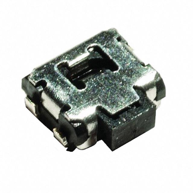
!
NEW
PTS 840 Series
Microminiature SMT Side Actuated
Features/Benefits
• 3.5 x 3.55 mm footprint
• Front PIP leads option for
Typical Applications
• Nomad devices
• Remote controls
• Personal health diagnostics
• Consumer electronics
strong shear resistance
• ESD pin option
• Reduced footprint
Tactile Switches
B
Specifications
Electrical
FUNCTION: momentary action
CONTACT ARRANGEMENT: 1 make contact = SPST N.O.
TERMINALS: J, G and front PIP types for SMT
TRAVEL: 0.2mm + 0.2mm / -0.1 mm
LIFE: 100,000 cycles
MAXIMUM VOLTAGE:
MAXIMUM CURRENT DC:
DIELECTRIC STRENGTH:
CONTACT RESISTANCE:
INSULATION RESISTANCE:
BOUNCE TIME:
Type
without ground pin
Operating
Force (gf)
SMT
Leads
Pegs
PTS840 GM SMTR LFS
PTS840 GK SMTR LFS
PTS840 JM SMTR LFS
PTS840 JK SMTR LFS
PTS840 PM SMTR LFS
PTS840 PK SMTR LFS
PTS840 GMP SMTR LFS
PTS840 GKP SMTR LFS
PTS840 JMP SMTR LFS
PTS840 JKP SMTR LFS
with ground pin
PTS840 ESDGM SMTR LFS
PTS840 ESDGK SMTR LFS
PTS840 ESDJM SMTR LFS
PTS840 ESDJK SMTR LFS
PTS840 ESDPM SMTR LFS
PTS840 ESDPK SMTR LFS
PTS840 ESDGMP SMTR LFS
PTS840 ESDGKP SMTR LFS
PTS840 ESDJMP SMTR LFS
PTS840 ESDJKP SMTR LFS
160
220
160
220
160
220
160
220
160
220
-40/+70
-70/+80
-40/+70
-70/+80
-40/+70
-70/+80
-40/+70
-70/+80
-40/+70
-70/+80
G leads
G leads
J leads
J leads
P leads
P leads
G leads
G leads
J leads
J leads
No
No
No
No
No
No
Yes
Yes
Yes
Yes
160
220
160
220
160
220
160
220
160
220
-40/+70
-70/+80
-40/+70
-70/+80
-40/+70
-70/+80
-40/+70
-70/+80
-40/+70
-70/+80
G leads
G leads
J leads
J leads
P leads
P leads
G leads
G leads
J leads
J leads
No
No
No
No
No
No
Yes
Yes
Yes
Yes
12 VDC
50 mA
250 VA C (1mn)
≤ 500 mΩ
≥ 100 MΩ
≤ 10 ms
Environmental
OPERATING TEMPERATURE:
-40˚C to 85˚C
Process
SOLDERING: This component is suited to the following methods:
Infrared Reflow Soldering in accordance with IEC61760-1
Packaging
In reels of 3,500 pieces
Dimensions of reels according to EIA 481B
External diameter 330 mm
NOTE: Specifications listed above are for switches with standard options.
For information on specific and custom switches, consult Customer Service Center.
How To Order
Our easy build-a-switch concept allows you to mix and match options to create the switch you need. To order, select
desired option from each category and place it in the appropriate box.
For any part number different from those listed above, please consult your local representative.
P
T
S
8
4
S M T
0
ESD Pin
VOID No
ESD Yes
R
L
F
S
LFS RoHS, silver plated
SMT Style
J J bend
G Gullwing
P Front PIP
Packaging
SMTR Tape & reel
Pegs*
P with pegs
Void no pegs
Actuation Force
M 160 gf
K 220 gf
* Peg option not valid for P SMT leads type
Design Recommendations
- “J” leads need to be soldered with 0.1mm solder paste thickness. Below this value, shock resistance will be decreased. A “G” lead version could easily replace it.
- “P” leads are recommended for applications where shear resistance is of importance
- When a precise alignment between application button and the switch is requested, version with pegs are the right choice to limit the possible floating of the switch
during solderability.
Dimensions are shown: mm
Specifications and dimensions subject to change
11 june 13
B–24
www.ck-components.com
�!
NEW
PTS 840 Series
Microminiature SMT Side Actuated
0,6
Standard J and G SMT Leads with ESD and Peg options
0
4,3 -0,05
5
Surface Mounting J Style
1
2
3
4
0,5
1,35
B
SCHEMATIC
This ground pin is for ESD function
only and not solderable
Ground terminal can
0±0,05
be effective even if
not soldered
5±0,1
2,2±0,1
1,1±0,1
1
2
3
4
2x
1
+0,2
0,7 -0,1
RECOMMENDED PCB LAYOUT
20
0,05
Scale
Max
0,1 Max
1,7
1,8±0,05
4
3
2,5±0,1
0,4±0,1
1,8±0,1
2
1,5±0,1
3,55
2,9
1
1,45±0,1
1,95±0,1
4,7
3,5
0,5
5
0,6
0,5
0,2
PCB MOUNTING
FACE
P SMT Leads with ESD option
SCHEMATIC
5
PCB MOUNTING
FACE
3
4
This ground pin is for ESD function
only and not solderable
1
4
1
0,6
0 ,1 Max
1,7
0 ,5 ± 0,1
3
2 ,5 ± 0,1
0 ,4 ± 0,1
2
Ground terminal can
be effective even
if not soldered
2 Ø 0,65 +0,1
0
Through hole
metalized
1,1
5
1
2
1,9 5 ± 0,1
5
1,45 ± 0,1
0 ,6
1,35
0±0,05
5,5±0,1
2,2±0,1
4
3
4,05±0,1
0 ,8 ± 0 ,1
3,5
0,5
0 ,5
0, 2
2 ,9
1 ,5 ± 0,1
2
3,9±0,15
4,7
3, 55
1
0 ,0 5 Max
RECOMMENDED PCB LAYOUT
Dimensions are shown: mm
Specifications and dimensions subject to change
11 june 13
B–25
www.ck-components.com
Tactile Switches
0
0,65 -0,1
Surface Mounting G Style
�!
NEW
PTS 840 Series
Microminiature SMT Side Actuated
TAPE & REEL
4
1 ,7 5
1,5
2
5 ,5
CARRIER TAPE
1 2 ± 0 ,3
9 ,3
C o v e r ta p e
Tactile Switches
B
8
18,4 Max
12,4+2
0
330
13± 0,5
2±0,5
21± 0,8
VOIR DETAIL A
DETAIL A
SCALE 0,5
REEL
Dimensions are shown: mm
Specifications and dimensions subject to change
11 june 13
B–26
www.ck-components.com
�
